
What is an HV cable joint?
An HV cable joint is a permanent electrical and mechanical connection that restores a cable's original insulation, screening and earth continuity at the point where two lengths meet – or where cable transitions to switchgear.
While a rigorous, professionally executed installation ensures decades of reliable performance, any oversight makes the joint the most critical point of failure on the circuit.
This guide covers the voltage ranges jointing spans, the joint and termination types involved, what typically causes a joint to fail, and the quality markers a client should expect to see on site before a joint is signed off.
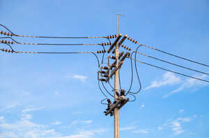
Joints, terminations, and their unique failure risks
In simple terms, a joint connects cable to cable. A termination, meanwhile, connects a cable to electrical equipment, typically switchgear, a transformer bushing, or an overhead line.
Both procedures involve stripping back the cable's outer sheath, armour, screen and insulation to expose the conductor, then rebuilding that layered structure around the new connection so the finished joint or termination performs the same electrical role as the cable either side of it.
The distinction is crucial because the failure modes differ. A joint's weak point is usually the interface between the two cable ends, where any mismatch in insulation type or any contamination introduced during preparation can create a void.
A termination's weak point is usually the transition to open air, where creepage distance, weatherproofing and UV resistance become as important as the electrical connection itself.
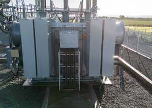
Voltages: what changes as you go up the range
HV cable jointing typically spans 11kV to 132kV, and the jointing technique, materials and testing regime all change as voltage increases.
At 11kV and 33kV, heat-shrink and cold-shrink jointing kits are common, and the tolerances for insulation build-up are more forgiving.
At 132kV, jointing moves to pre-moulded or push-fit interfaces engineered to far tighter dimensional tolerances, because the electrical stress across the insulation at transmission-adjacent voltages leaves very little margin for error in the joint geometry.
A joint that would perform acceptably at 11kV can fail rapidly at 132kV if the same workmanship standard is applied.
This is also where legacy cable creates complications.
A large proportion of the UK's HV network still uses paper-insulated lead-covered (PILC) cable, particularly at 33kV and below, which is now commonly jointed to modern XLPE cable during reinforcement and connection works.
Transition joints between PILC and XLPE require specific kits and sealing methods, because the two insulation types behave differently under electrical and thermal stress, and a joint built as if both cables were the same material is a prevalent source of early failure.
Optimi, the Heighway Group’s expert division for Extra High Voltage (EHV) design, protection and commissioning, works up to 400kV.
For voltages between 11kV and 132kV, Heighway Energy provides a completely self-delivered jointing service. By directly employing every jointer, rather than relying on subcontractors, the division ensures total quality control.
What are the joint and termination types?

Straight, or inline, joints connect two lengths of the same cable type and are the most common jointing operation on any HV programme, required for fault repairs, extending a circuit, or connecting a new section to an existing network.
Transition joints connect two different cable types, most often PILC to XLPE, and carry the highest installation risk among joint types – chiefly because the kit must manage two different insulation behaviours at a single interface.
Branc, or T, joints connect a spur to a main run without breaking continuity along the main cable and are more exposed to installation errors because there are more interfaces to seal correctly.
Terminations split into indoor and outdoor
Indoor sealing ends are used where a cable meets switchgear inside a building or enclosure; they're protected from weather but still need to manage electrical stress at the point where the cable's screen terminates.
Outdoor sealing ends are used at overhead line connections, substations, and open compounds; they need sufficient creepage distance and the right insulator material, porcelain, composite, or silicone, to withstand pollution, salt deposition, and UV exposure over the asset's service life.
Choosing the wrong termination type for its environment is one of the more common causes of premature failure in outdoor HV assets, because the problem often does not show up until the insulator has been weathering for a year or two.
Why JV joints fail
A small number of root causes account for most HV joint and termination failures, and nearly all are installation issues rather than design flaws.
The table below sets out the common failure modes alongside the on-site controls that catch them before the joint is closed up and energised.
| Failure mode | What typically causes it | What controls it on site |
| Partial discharge from voids or contamination | Dust, moisture or debris introduced during core preparation, or an air gap left in the insulation build-up | Jointing carried out in a clean, controlled enclosure; partial discharge testing before energisation |
| Moisture ingress and water treeing | Damaged outer sheath, poor sealing at the joint casing, or exposure to standing water before backfill | Sealed, pressure-tested casings; VLF withstand testing to confirm insulation integrity |
| Insulation breakdown at a transition interface | PILC-to-XLPE or other mixed-insulation joints built without a transition-specific kit | Correct kit selection matched to both cable types; manufacturer-approved procedure followed exactly |
| Thermal failure at the connector | Under-torqued or over-torqued mechanical or compression connectors, or contamination on the conductor | Torque values recorded against the manufacturer's specification; connector surfaces cleaned and checked before crimping |
| Tracking or flashover at an outdoor termination | Insufficient creepage distance or the wrong insulator material for the site's pollution level | Termination type and insulator material specified against the site environment, not a default selection |
| Screen or earth discontinuity | Screen not correctly bonded or terminated through the joint | Continuity testing on completion, before the joint is backfilled or closed |
What quality on site looks like
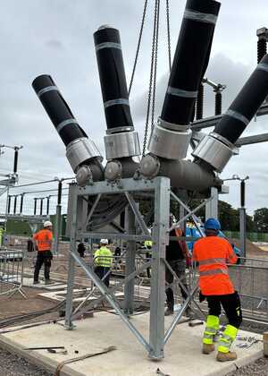
A client cannot see inside a finished joint, so the important quality markers are those visible in the site setup and work environment:
Environmental controls
Jointing requires a tented or otherwise controlled environment that keeps dust, moisture and wind off the open cable core during preparation. An HV joint made in the open on a wet or dusty site carries a materially higher risk of the contamination-driven failures in the table above, however competent the jointer.
Kit specification and selection
The jointing kit should be selected based on the cable's manufacturer and insulation type, not treated as a generic fitting. Heighway's jointers work across Nexans, Pfisterer, TE Connectivity and Prysmian systems, and kit selection is made against the network specification and cable type on that job, not a single preferred supplier.
Pre-commissioning testing
Before a joint is closed and backfilled, or a termination is energised, there should be a documented test result confirming it:
VLF withstand testing verifies that the insulation can withstand the operating voltage.
Tan delta testing measures dielectric loss and flags insulation degradation that a simple withstand test would miss.
Partial discharge testing detects the voids and contamination that cause the most common long-term failure mode, before the joint is ever put into service.
A client should expect to see these results as part of handover, not just a completion certificate.
Quality records and traceability
Photographic records at each build stage, torque records for every mechanical connection, and a named sign-off from the jointer and an authorised person are standard practice on a well-run HV programme.
Alongside immediate quality assurance, the data acts as a permanent operational reference; a joint made in 2026 may need to be found, identified, and fault-traced in 2046, making the contractor's records the only reliable evidence of what is buried in the ground.

The commercial value of direct employment
Every jointer Heighway puts on a live programme is a permanent employee, not an agency fitter or a subcontracted crew.
Minimising failure rates across a large HV programme depends on consistent workmanship – and direct employment secures the same high standards far more effectively than rotating subcontract crews. The same internal teams work to identical installation methods on the same manufacturer systems, joint after joint.
Self-delivery also provides long-term operational accountability. When a fault is traced back to a joint years after installation, a client is dealing with the same organisation that executed the work – instead of chasing an historical subcontractor who may no longer hold the contract, or even exist.
Frequently asked questions
What is the difference between an HV cable joint and a termination?
A joint connects cable to cable. A termination connects a cable to switchgear, a transformer, or an overhead line, and must manage the transition to open air rather than just the interface between two cable ends.
What voltage range does Heighway self-deliver for cable jointing?
11kV to 132kV, with every jointer directly employed rather than subcontracted. Design and commissioning above 132kV, up to 400kV, is delivered through Optimi.
What causes most HV joint failures?
Contamination or voids in the insulation build-up, moisture ingress through poor sealing, mismatched kit on transition joints between different cable types, and under- or over-torqued mechanical connectors. Most trace back to workmanship rather than the design of the joint itself.
What tests should a new HV joint pass before energisation?
A VLF withstand test to confirm the insulation holds at operating voltage, a tan delta test to check for dielectric degradation, and partial discharge testing to detect voids or contamination. Results should be provided at handover.
Why does jointing PILC to XLPE cable need a different approach?
The two insulation types behave differently under electrical and thermal stress, so a straight joint built as if both cables were the same material is a common source of early failure. Transition joints require a specific kit and sealing method for the interface.
Get in touch
If you are scoping HV cable jointing for an upcoming programme, discuss your requirements with our team or download the Heighway Energy capability statement.
Posted on September 10th 2026
 Updating page...